


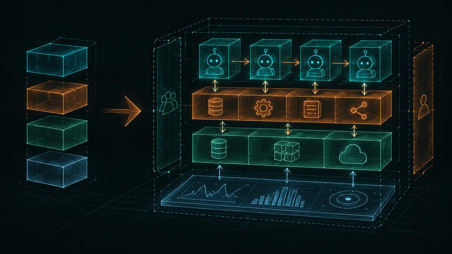
Architecture diagrams fail when they try to be complete before they are useful. The goal is not a perfect picture. It is to externalize the current reasoning so the next design decision has somewhere to live.
Start with four boxes
1User2↓3Application / Auth4↓5Agent Runtime6↓7Tools / RetrievalDo not begin with queues, vector databases, event buses, caches, and observability. Draw only the happy path needed to explain the first architectural decision.
Draw left-to-right for execution, top-to-bottom for boundaries
A consistent visual grammar prevents the diagram from becoming a maze. Execution moves horizontally or left-to-right. Trust, responsibility, or lifecycle boundaries can be stacked vertically.
1USER PLANE2User → App/Auth → Agent1CAPABILITY PLANE2↓3Retrieval / Tools1AUTHORITY PLANE2↓3Policy / Systems of RecordAdd boxes only when a requirement earns them
| Requirement appears | Add |
|---|---|
| Long-running task | Queue + durable job/workflow |
| Side effects | Policy/authorization boundary + system of record |
| Unstructured knowledge | Retrieval/RAG path |
| High scale | Worker pools, quotas, queues, concurrency limits |
| Partial failure | Durable workflow state + idempotency |
| Multi-tenant data | Trusted identity + ACL filtering |
| Need to improve quality | Tracing/eval system outside runtime |
Worked example: enterprise knowledge agent
First, establish the happy path.
Employee → Authenticated App → Agent Runtime
Next, add the knowledge-access path.
1Employee → App/Auth → Agent Runtime → Retrieval2↓3Live ToolsThen add the access-control requirement.
1Trusted user identity2↓3ACL-aware Retrieval4↓5authorized chunks only6↓7Agent RuntimeAdd a guarded path for write actions.
1Agent proposes action2↓3Policy / AuthZ4↓5Narrow tool adapter6↓7System of recordAdd durable execution for long-running actions.
1Agent2↓3Create durable job4↓5Queue6↓7Workflow / workers8↓9Systems of recordFinally, add the measurement loop.
1Production Runtime ─────────────→ Traces2↓3Eval dataset → Eval runner → graders → release gateThe diagram grew because requirements demanded new responsibilities. That makes it easier for a team to review than a complete production topology presented all at once.
The box-placement rules that prevent getting stuck
- Put the user and entry point first.
- Put the agent runtime before its capabilities; the runtime consumes tools rather than becoming the tool.
- Keep systems of record visually downstream of tool/policy boundaries.
- Place queues between producers and asynchronous consumers, not randomly beside the agent.
- Place authorization in front of side effects, not inside the LLM box.
- Place evals beside/outside the production runtime; they test the system rather than execute the user request.
- Put observability across components, because tracing is cross-cutting.
Make ownership explicit
Every box should answer one sentence: what does this component own? This keeps the diagram from becoming decorative.
1Agent Runtime:2semantic reasoning + tool loop1Policy Service:2authorization + business constraints1Workflow:2durable known process1System of Record:2authoritative state1Eval Harness:2quality measurement outside productionA sequence for untangling complex designs
When a design becomes difficult to reason about, return to this sequence:
11\. Outcome22. Autonomy33. Boundary44. Prove55. Operate66. OptimizeOutcome: what must the system accomplish? Autonomy: what should the model decide? Boundary: what must deterministic systems control? Prove: how will correctness be evaluated? Operate: how will it fail and recover? Optimize: where do latency and cost matter?
Three architecture scenarios
- Design an internal agent that answers company questions and can update constrained CRM.
- Design a support agent that can refund orders but must never exceed policy limits.
- Design a research agent for 10,000 employees with long-running background jobs and strict tenant isolation.
For each scenario, draw progressively. Every new box should have a clear responsibility and trace back to a concrete requirement.
# Practical reference — where each control lives
| Concept | Where it lives | What it prevents |
|---|---|---|
| Autonomy budget | Agent runtime / orchestration layer | Runaway turns, tool calls, cost, side effects |
| Backpressure | Between producer and constrained dependency | Downstream overload |
| Admission control | Ingress / scheduler | Accepting work the system cannot service |
| Reserved capacity | Scheduler / worker allocation | Starvation |
| Aging | Scheduler | Indefinite waiting of low-priority jobs |
| Idempotency | Tool/service boundary | Duplicate side effects on retry |
| ACL enforcement | Retrieval/tool service using trusted identity | Cross-user or cross-tenant data leakage |
| Policy checks | Deterministic backend before side effect | Model-granted authority |
| Eval harness | Outside production runtime | Unmeasured regressions |
| Tracing | Across runtime, model, tools, workflows | Opaque failures |
| Durable workflow | Workflow service / state store | Loss of multi-step progress |
| Queue | Between async producer and consumer | Burst propagation |